

 +44 3308180992
Research Article - International Research Journal of Engineering Science, Technology and Innovation ( 2025) Volume 11, Issue 2
Received: 11-Nov-2024, Manuscript No. IRJESTI-26-152144; Editor assigned: 14-Nov-2024, Pre QC No. IRJESTI-26-152144 (PQ); Reviewed: 28-Nov-2024, QC No. IRJESTI-26-152144; Revised: 08-Jun-2025, Manuscript No. IRJESTI-26-152144 (R); Published: 15-Jun-2025, DOI: 10.14303/2315-5663.2025.129
Current hydraulic brake master cylinders with larger bore sizes require more operational force, leading to increased physical strain on drivers. Additionally, these larger cylinders tend to be heavier, which adversely impacts vehicle performance due to the additional weight and less optimized materials. The motivation for this project arises from the need to enhance braking systems by reducing human effort and optimizing material weight. This is especially pertinent in automotive applications, where reduced component weight can improve overall vehicle performance. By focusing on a smaller bore size, the project aims to create a more efficient and user-friendly braking system, ultimately contributing to improved driving comfort and safety.
Hydraulic brakes, Master cylinder, Analysis, Design calculation, Braking force calculation
The brake master cylinder is an essential component in an automobile's braking system, responsible for converting mechanical force into hydraulic pressure, which is crucial for effective braking. This project focuses on the design of a master cylinder with a bore size of 15 mm, aimed at reducing the physical effort required during braking. By optimizing the design for depend ability and efficiency, this work seeks to enhance vehicle safety. This paper outlines the design considerations, material selection, and analytical methods employed to achieve these objectives, contributing significantly to the advancement of braking system technology (Bhandari, 2010).
Master cylinder
The brake master cylinder is the central pressure pump in an automobile's braking system. It converts the mechanical force from the brake pedal into hydraulic pressure by compressing brake fluid in the lines. This pressurized fluid is then directed to the brake caliper, where it moves the caliper piston, causing the brake pads to press against the rotor and stop the vehicle. The master cylinder has two primary ports: An inlet and an outlet. The inlet port is further divided into a breather port and a compensating port. The breather port prevents a vacuum from forming within the master cylinder, ensuring smooth operation (Waughtal, 2003).
• The master cylinder is a crucial component of thehydraulic brake system, consisting of several partsthat work together to ensure efficient brakingperformance. At the heart of the system is thepiston, which moves inside the cylinder togenerate hydraulic pressure. This movement isinitiated by the pushrod, which connects to thebrake pedal. When the driver presses the brakepedal, the pushrod pushes the piston, forcing thehydraulic fluid to flow through the system.
• The cylinder housing encloses the piston, providinga sealed environment for its movement. Seals are positioned around the piston to prevent any leakage of brake fluid, ensuring that the system maintains its pressure. When the brake pedal is released, the return spring pushes the piston back to its original position, allowing the fluid pressure to decrease and the brakes to disengage.
• Two important ports, the compensating port andthe breather port, regulate fluid flow and pressurewithin the system. The compensating port allowsbrake fluid to flow between the reservoir and thecylinder bore, ensuring that the system remains filled and pressure is equalized. The breather port, located just behind the compensating port, becomes uncovered when the piston is fully retracted, enabling fluid communication with the reservoir and maintaining proper fluid levels in the system.
Together, these components work seamlessly tocreate a responsive and efficient braking system,ensuring that the vehicle can brake safely andeffectively under various conditions (Figure 1).
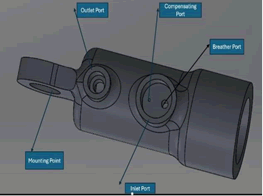
Figure 1. Parts of brake master cylinder.
The Tilton 78 Series master cylinder is selected as reference for the design due to its minimal bore size of 15.88 mm, stroke length of 27.94 mm and efficient bearing mount configuration. These features make it an ideal benchmark for the design, offering the necessary precision and efficiency. Although other options like AP Racing, Wilwood, and Girling are available, they typically feature fixed mounting points and bore sizes exceeding 19 mm, which do not align with desired design objectives. Consequently, the Tilton 78 Series was the most suitable choice for desired reference (Figures 2 and 3).
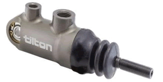
Figure 2. Existing model of brake master cylinder in the market (Tilton 7,8 series).
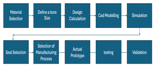
Figure 3. Flowchart indicating the process.
In order to minimize driver effort and increase efficiency, optimizing master cylinder design is a critical area of focus. Hydraulic braking systems are essential for vehicle safety and performance. In his analysis of hydraulic pressure distribution in brake systems, Limpert points out that smaller master cylinder bore sizes can result in less pedal effort being needed. In a similar vein, Puhn addresses the trade-off between stroke length and bore size, with smaller bores possibly requiring more pedal travel but requiring less force overall. The current study uses a 15 mm bore size, which strikes a compromise between less driver effort and enough stroke length for responsive braking, to address these issues. Another crucial consideration is material choice. Buynacek and Winterbottom recommended using aluminium alloys in brake systems because of their excellent strength-to-weight ratio. As indicated by Bhandari, the current project uses Aluminium 6061 T6 for the master cylinder in order to reduce weight and increase vehicle efficiency. According to Hi-Tech Seals Inc. and Melior Inc., proper sealing guarantees that hydraulic systems keep pressure and stop fluid leaks. O-rings and U-cup seals are particularly picked for their robustness and suitability for the system's operating pressures. According to Kim and Lee, SolidWorks was used to perform Finite Element Analysis (FEA), which confirmed the structural integrity of the master cylinder and piston under high pressure. The results showed a factor of safety of 1.58 for the piston and 3.13 for the master cylinder. The project's objective of reducing weight through advanced materials was backed by Waughtal. This led to a 60-gram weight reduction in the master cylinder, improving the overall dynamics of the vehicle. In order to create a hydraulic brake master cylinder that is more effective and user-friendly, this project incorporates these findings, which will enhance performance, safety, and driver comfort.
Material and seal selectiom
Aluminium 6061-T6 is selected for design due to its exceptional strength-to-weight ratio, corrosion resistance, and machinability. This alloy offers the necessary strength to endure the high pressures within the master cylinder while maintaining a lightweight structure, which is essential for optimizing overall vehicle efficiency. Furthermore, its corrosion-resistant properties contribute to the long-term durability and reliability of the component, even in harsh automotive environments. To ensure effective fluid control within the master cylinder, a U-seal made of EPDM (Ethylene Propylene Diene Monomer) is selected for its one-way sealing capability, which is particularly suited for creating pressure in a single direction. EPDM is chosen because it offers superior resistance to glycol-based brake fluids, making it more suitable than NBR (Nitrile Butadiene Rubber), which can swell or degrade in contact with such fluids. Additionally, an EPDM O-ring is chosen to prevent leakage around the stopper piston, providing a reliable seal that maintains system integrity. Both EPDM seals are meticulously selected for their compatibility with the required pressure rating and operational lifespan, ensuring consistent and durable performance under demanding conditions (Tables 1 and 2) (Limpert, 1999).
| Material | Dimensions | Rating |
| O ring EPDM | 21 × 1.5 | 103 bar |
| O ring EPDM | 10 × 1 | 103 bar |
| O ring EPDM | 16 × 2 | 103 bar |
| U seal EPDM | 9.7 × 14.7 × 5 | 350 bar |
Table 1. Specification of seals.
| Material | Yield strength (mPa) | Ultimate tensile strength (mPa) | Hardness (Brinell's scale) | Density (kg/m3) | Poisson's ratio | Cost (rupees/kg ) |
| Al 7075 T6 | ~503 | ~572 | 150 | 2810 | 0.33 | 490 |
| Al 6061 T6 | ~275 | ~310 | 95 | 2700 | 0.33 | 345 |
| Al 6063 T6 | ~215 | ~240 | 73 | 2700 | 0.33 | 400 |
| Al 5052 H32 | ~195 | ~230 | 60 | 2680 | 0.33 | 350 |
| SS 304 | ~215 | ~505 | 123 | 7930 | 0.29 | 190 |
| SS 316 | ~240 | ~550 | 149 | ~8000 | 0.28 | 255 |
Table 2. Material selection.
Selection of bore size
Design process for the hydraulic brake master cylinder is initially aimed to decrease the bore size to reduce the effort required for braking. However, reducing the bore size also results in an increase in stroke length, which directly affects the brake system’s performance. A smaller bore size requires a longer stroke to displace the same volume of brake fluid, leading to excessive pedal travel and potentially creating a spongy feeling in the brake pedal, which compromises the system's responsiveness. Through careful analysis and calculations involving the relationship between bore size, applied effort, and stroke length, a bore size of 15 mm that offers the optimal balance is determined. Bore sizes smaller than 15 mm, while reducing effort, resulted in significant compromises in stroke length, causing excessive pedal travel and a less responsive braking system. Therefore, 15 mm was selected as the ideal bore size to provide efficient braking without sacrificing pedal feel or system responsiveness (Table 3 and Figure 4) (Kim and Lee, 2016).
| Bore size | Stroke-length | Pedal force in kg |
| 12 | 48.92884 | 18.61 |
| 13 | 41.69084 | 21.84 |
| 14 | 35.94772 | 25.33 |
| 15 | 31.31446 | 29.08 |
| 16 | 27.52247 | 33.09 |
| 17 | 24.37977 | 37.36 |
| 18 | 21.74615 | 41.88 |
Table 3. Bore size, stroke length and corresponding pedal force.
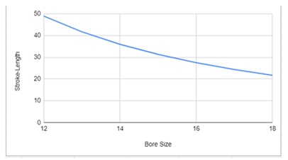
Figure 4. Graph of bore size vs. stroke length.
Design calculation
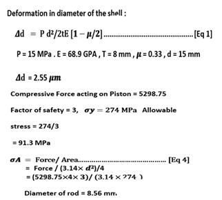
Through precise calculations, a minimum rod diameter of 9 mm is required to withstand the necessary force is established. However, to enhance safety margins and account for potential operational variances, 10 mm diameter is prudently selected. This strategic increase ensures the rod possesses the requisite strength and resilience to endure the anticipated stresses, thereby safeguarding the integrity and reliability of the overall system (Table 4) (Park et al., 2021).
| Component | Dimension | Component | Dimension |
| Piston diameter | 15 mm | Discharge of brake fluid from master cylinder | 7065 mm3 |
| Piston length | 135 mm | Diameter of push rod | 10 mm |
| Diameter of master cylinder | 15 mm | Hoop stress Generated in the master cylinder | 140.6 MPa |
| Stroke length of master cylinder | 40 mm | Area of master cylinder | 176.625 mm2 |
| Thickness of master cylinder | 8 mm | Deformation in diameter of shell | 2.55 µm |
Table 4. Master cylinder and piston specifications.
Braking force calculation
Detailed theoretical analysis is conducted to confirm that a smaller bore size demands less force, as dictated by Pascal's law. According to this law, in a confined fluid, any change in pressure is transmitted equally throughout the fluid, allowing us to manipulate force and area to achieve desired outcomes. Using data from an FSG (Formula Student Germany) car, analysis of the braking force bias and the pressure within the brake hose is done. Calculation of the pedal force required for various bore sizes is done and graph is plotted to illustrate these relationships. The graph demonstrates that as the bore size increases, the required force also increases. This outcome substantiates our theoretical calculations, validating that a smaller bore size effectively reduces the force needed, in precise alignment with Pascal's law (Figure 5 and Table 5) (Martinez, 2018).
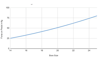
Figure 5. Force on pedal vs. bore size.
| Input | Value | Unit | Weight transfer | 49.24706 |
| Mass of vehicle | 230 | Kg | Weight tranfer on front wheel | 161.2471 |
| Mass of vehicle on front wheel | 112 | Kg | Weight transfer on rear wheel | 68.75294 |
| Mass of vehicle on rear wheel | 118 | Kg | Force on front piston | 4378.649 |
| Decceleration of car | 1.2 | m/s2 | Force on rear piston | 1866.98 |
| Acceleration due to gravity | 9.8 | m/s2 | Pressure in front hose | 56.57326 |
| Height of Cg | 0.273 | m | Pressure in rear hose | 24.12185 |
| Wheel base | 1.53 | m | Force on front Mc piston | 999.2252 |
| Outer diameter of disc | 0.21 | m | force on rear Mc piston | 426.0522 |
| Inner diameter of disc | 0.15 | m | Total force on balance bar | 1425.277 |
| Mean diameter of disc | 0.18 | m | Front bias | 70.10742 |
| Bore size of master cylinder piston | 0.015 | m | Rear bias | 29.89258 |
| Bore of caliper piston | 0.0314 | m | Force on pedal | 285.0555 |
| Area of master cylinder piston | 0.000177 | m2 | Force on pedal in kg | 29.08729 |
| Area of caliper piston | 0.000774 | m2 | ||
| Pad area | 0.11304 | m2 | ||
| Pad length | 0.03 | m | ||
| Coefficient friction of Pad | 0.55 | |||
| Coefficient friction of tyre | 1.2 | |||
| Tyre diameter | 0.4572 | m | ||
| Car speed | 25 | m/s | ||
| Time required to stop the car | 4 | sec |
Table 5. Braking force calculation.
Brake pedal geomentry
Solid works is used to design the geometry of the hydraulic brake system, focusing on the relationship between pedal actuation angle and stroke length. This helped to analyze how changes in pedal angle affect piston movement and fluid displacement. Study of the vertical brake assembly, commonly used in Formula Student Germany (FSG) cars is done, to optimize its performance. The vertical configuration allows for better ergonomics and easier adjustment of stroke length. By modeling these factors, it is ensured that pedal actuation remains smooth and the stroke length is optimized, avoiding excessive pedal travel while maintaining responsive braking. This design enhances the overall efficiency and performance of the brake system, making it ideal for high-performance FSG cars (Figures 6 and 7) (Johnson, 2012).
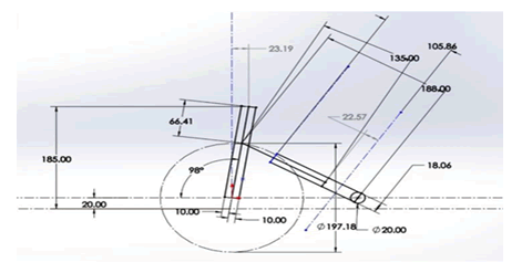
Figure 6. Brake pedal geometry with dimensional annotations.
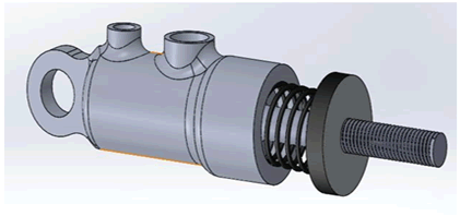
Figure 7. Assembly model.
Results are received through an extensive series of analyses to ensure the structural integrity and performance of the master cylinder and piston under various operating conditions, particularly considering a maximum pressure of 150 bar, which significantly exceeds the typical maximum pressure of 60 bar experienced during hard braking in vehicles (Figures 8 and 9) (Reddaiah, 2013).
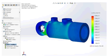
Figure 8. Von Mises static stress analysis of master cylinder at 5000 N.
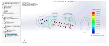
Figure 9. Von Mises stress analysis of master cylinder in point view.
These analyses included pressure analysis within the master cylinder, static structural analysis for both the master cylinder and piston, as well as buckling analysis of the piston. The static analysis of the master cylinder is performed with a force of 5000 Newtons, exerted as typically experienced from the brake pedal, while a force of 3000 Newtons is applied for the piston analysis, both under bearing mount conditions (Figures 10 and 11) (Ahmed, 2020).
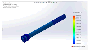
Figure 10. Von Mises static stress analysis of Piston at 3000 N.
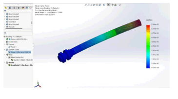
Figure 11. Buckling analysis of Piston at 3000 N.
All these analyses were meticulously executed using SolidWorks Simulation, ensuring a thorough evaluation of the components' resilience. The results indicated a Factor of Safety (FOS) of 3.13 for the master cylinder and 1.58 for the piston, with maximum and minimum stress levels confirming the robustness and reliability of the design under high-pressure scenarios (Table 6).
| Component | Maximum static stress | Minimum static stress | Material | FOS |
| Master cylinder | 80.076 MPa | 3.01MPa | Aluminium 6061 T6 | 3.13 |
| Piston | 223.9 MPa | 0.14MPa | Aluminium 6061 T6 | 1.58 |
Table 6. Result table.
In the detailed analysis, Aluminium 6061 T6 is selected for the master cylinder design due to its excellent strength-to-weight ratio, corrosion resistance, and machinability. This material choice ensures the component can withstand high operating pressures while maintaining a lightweight structure, crucial for vehicle efficiency. For sealing, a U-seal is chosen for its one-way sealing capability, ideal for maintaining pressure within the master cylinder. An O-ring is used to prevent leakage around the stopper piston, ensuring system integrity. Both seals are selected based on their compatibility with the required pressure rating and durability. the Formula Student Germany (FSG) car is selected for our analysis, where it is difficult to use a bore size smaller than 15 mm due to operating pressure constraints. Therefore, we selected a 15 mm bore size, referencing the Tilton 78 Series master cylinder, which has a bore size of 15.88 mm. This decision not only ensured operational efficiency but also allowed to reduce the weight of the master cylinder body by 60 grams, achieving a final weight of 117 grams. This design was validated through both theoretical calculations and simulation, confirming that the selected bore size and material meet the required performance standards (Figure 12).
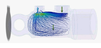
Figure 12. Fluid flow analysis.
The design and development of a hydraulic brake master cylinder with a 15 mm bore size represents a significant advancement in braking technology. By addressing challenges related to precise manufacturing, seal selection, and material constraints, and by overcoming the difficulties associated with achieving exact piston tolerances, the project successfully reduced human effort and optimized efficiency. This development not only enhances safety and performance in braking systems but also sets the stage for future innovations in automotive engineering.